You may be considering the use of ceramic membranes for your next filtration project but would like to know more about what they are and how they are employed.
When are they employed?
The largest worldwide use is for municipal waster water treatment. For industrial use they are employed when other methods are not suitable. Most common industrial uses are for fines removal smaller than 0.5 microns and high temperature fluids and gasses, aggresive solvents, acids, caustics, small footprint projects, fluids and gasses requiring an inert filter media, systems requiring automated continuous operation, oily water with surfactants or solids, heavy metals removal/recovery, and systems requiring temperature and/or chemical sterilization to protect the product.
How are they manufactured?
Ceramic membranes are manufactured from Silicon Carbide (SiC) as a support layer with the active membrane surface made from TiO2, SiO2, Al2O3, or SiC. Silicon Carbide is a synthetic product of silica sand and carbon. The membrane surface materials are overlayed to produce the various membrane pore sizes. SiC hardness and durability also makes it useful for automobile catalytic converter internals, high performance ceramic disk brake pads and synthetic diamonds.
What solids sizes may be filtered for removal?
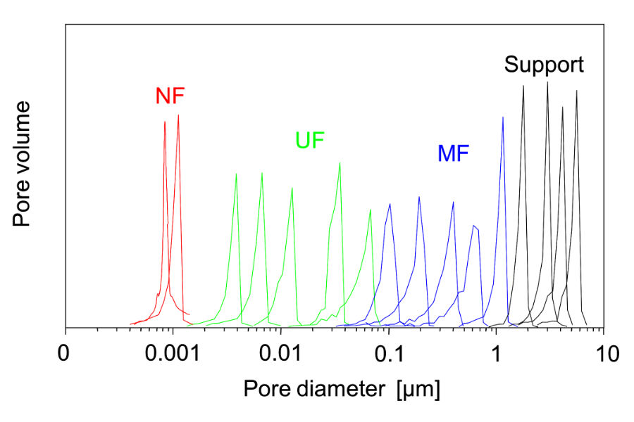
The membrane surface layer has pore sizes ranging from 10 microns to 5 nanometers. This covers the particle classification range from microfiltration, ultrafiltration to nano filtration. They are not tight enough however, to separate molecules or ions. For many applications, dissolved solids and heavy metals are chemically treated to produce a filterable suspended solid. C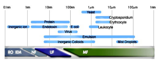 eramic membrane systems are not employed in the same way as reverse osmosis (R/O) membranes which remove ions or most commonly salt (NaCl) from seawater but for most drinking water applications as pre-filters to remove solids and oils to protect delicate downstream polymeric R/O membranes from fouling and damage. The individual ceramic elements may be tubular or flat plate with maximum temperatures to 400oC (750oF) and pH resistance ranging from 1 to 14.
What is cross-flow filtration?
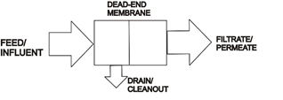
Flow may be dead-ended into the media or use tangential flow (cross-flow). Systems usually employ fluid pressure to drive the permeate through the membrane but may use a vacuum to draw the clean permeate fluid though as in submerged flat plate water treatment or pervaporation.

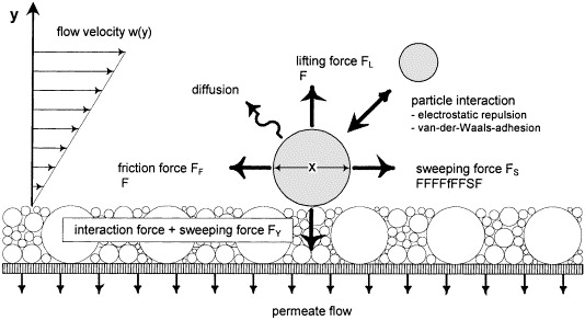
Cross flow systems employ sweeping forces at the membrane surface to reduce fouling as the permeate is removed resulting in the stream becoming more concentrated for batch processes as it is recycled and filtered to its maximum concentration factor.
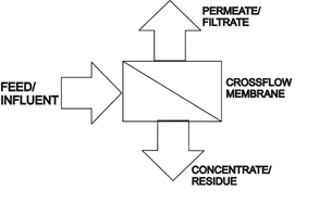
Crossflow filtration process flow diagrams:
Simplified Cross Flow Filtration Process is Shown Below:

A cross-flow design employs a large recycle stream that is sized to maintain a constant velocity in the membrane channels to sweep solids and foulants from the surface of the membrane. Two centrifugal pumps are recommended to maintain even system flow, a small feed pump with a larger recirculation pump. Pump pressure is much lower and less expensive that R/O applications, usually less than 2 bar. Pilot testing helps to determine optimum channel size and velocity in the membrane channels to optimize permeate flow and maximize run time between cleaning of the membrane surface. Cleaning is accomplished by employing the permeate to back pulse or backwash the system. Chemicals may also be employed to enhance the cleaning operation.
Expanded Process Flow Diagram

What pump pressures are required to achieve desired filtration?
Membrane Pore |
Molecular Mass |
Process |
Filtration Pressure |
Removal Cutoff |
> 0.1 μm |
> 5000 kDa |
microfiltration |
< 2 bar |
larger bacteria, yeast, particles |
100-2 nm |
5-5000 kDa |
ultrafiltration |
1-10 bar |
bacteria, macromolecules, proteins, larger viruses |
2-1 nm |
0.1-5 kDa |
nanofiltration |
3-20 bar |
viruses, valent ions |
< 1 nm |
< 100 Da |
reverse osmosis |
10-80 bar |
salts, small organic molecules |
More details about when and why they are employed.
In what circumstances are ceramic membranes chosen instead of polymeric membranes, dead- end disposable filters, filter presses, disc filters, liquid/liquid coalescers, distillation, or centrifugal separators? Some obvious applications are apparent such as those requiring continuous unattended operation, fines below 0.5 microns, temperature sensitive components, delicate solids required for reuse, concentration of retentate for reuse or disposal scenarios, emulsions, azeoptropes, reactive/short life components, high temperature liquids and gasses, aggressive solvents, acids, hydrocarbons, corrosive liquids/gasses, and radioactive materials.
Ceramic membranes are robust and last many years in harsh environments. The membrane elements can be cleaned by back pulsing, back washing, solvent cleaning or steam & chemical sterilization, or autoclaving. They can be manufactured to be highly hydrophilic, hydrophobic, and oleophobic. Usually, a real-world ceramic cross-flow filtration system includes a combination of technologies such as settling tanks, prefilter screens, centrifuges, hydrocyclones, distillation, chemical pretreatment, drinking water R/O membranes and more.
Your process may be better suited to a continuous automated self-cleaning system rather than disposable media. Your streams may have very fine particles that are difficult to remove or they may be required to be captured and recycled back to the process. The streams may also be delicate, temperature sensitive, very hot, corrosive, or explosive. Your process equipment may require treatment with chemicals, steam or high temperature alkaline solutions to maintain a sterile system and product. Polymeric membranes may have limited life due to your process conditions. Or, you may want a ceramic system that will simply offer you a long-lasting stable filtration system you can count on for years.
Lets take a look at membrane elements.
A Tubular Multi-Channel Ceramic Membrane Element is Shown Below:
Tubular Membrane Element Cross-Section
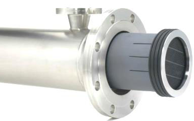
Membrane Element and Stainless-Steel Housing
Shapes and Styles of Ceramic Membranes are Numerous.
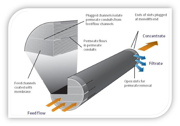
.jpg) A ceramic membrane element design includes the support media type, the surface membrane media type, channel size/shape/length, and sealing method for the element. The goal is to maximize filter surface area and flux while minimizing fouling caused by channel diameters too small for the solids in the feed stream. The trans-membrane pressure requirements will be higher for thicker support walls and backflushing will be more difficult and manufacturers try to optimize their design for the type of processes they wish to target. Of course the cost to manufacture the element, the element physical strength, and the elements thermal stability must be considered. Elements easily damaged during fabrication, installation, or from normal process thermal changes and removal for required maintenance work should be avoided.
A ceramic membrane element design includes the support media type, the surface membrane media type, channel size/shape/length, and sealing method for the element. The goal is to maximize filter surface area and flux while minimizing fouling caused by channel diameters too small for the solids in the feed stream. The trans-membrane pressure requirements will be higher for thicker support walls and backflushing will be more difficult and manufacturers try to optimize their design for the type of processes they wish to target. Of course the cost to manufacture the element, the element physical strength, and the elements thermal stability must be considered. Elements easily damaged during fabrication, installation, or from normal process thermal changes and removal for required maintenance work should be avoided.
Additional Design Considerations Include:
-
High membrane area to module bulk volume ratio
-
High degree of turbulence for maximized mass transfer on the feed side
-
Low energy expenditure per unit permeate volume
-
Low cost per unit membrane area
-
Designs which facilitate cleaning-
-
Designs which facilitate modularization
How do I select the correct membrane element pore size?
The pore structure of a ceramic membrane may have a wide or tight size distribution allowing for targeted particle removal. Ceramic membranes are not absolute rated however when targeting a particular size range or an individual particle size for removal, the options available for distribution size of the membrane can be selected for your project objectives. If the pore spectrum is wide, it will allow a wider size range of solids to pass through.
The target is to remove all particles larger than the selected pore size but since these filters are not absolute rated for one particle size, a small percentage of unwanted particles may pass through to the permeate. A smaller pore size may improve the results. Process data and particle characterization tests will help you and your supplier choose the correct elements.
Narrow Pore Size Distribution

Typical Spectrum Wide, Pore Size Distributions
What about filtration element housings?
Ceramic membrane systems may be housed in stainless steel, CPVC, or fiberglass housings with seals determined by the fluid temperature and composition.
Industrial wastewater treatment employing flat plate membranes.
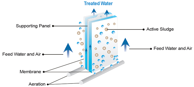
Flat sheet ceramic membranes are commonly employed as submerged membrane bioreactors (SMB’s) for wastewater treatment. Ceramic flat plate membranes are directly submerged in the bioreactor and a vacuum is applied to draw the wastewater into the membrane. Air bubbles are employed below the membrane to feed the activated sludge and also clean the surface of the membrane. These are also backflushed to remove foulants.
Submerged Flat Plate Membrane
Ceramic Crossflow membranes are similar to Reverse Osmosis membranes but ceramic membranes are designed to remove suspended solids, not dissolved solids or ions. Ceramic Crossflow membrane systems are employed for oily water, wastewater, caustics, acids, laundry rinse water, heavy metals removal, brine, bacteria separation, and clarification of beer and wine. Unlike many polymeric membranes, ceramic membranes are naturally hydrophilic and do not require pre-treatment wetting or solvent rewetting to be hydrophilic.
Common terms employed for defining ceramic filtration systems:
Membrane Pore Size-the size of the open channel structure allowing filtered permeate to pass and rejecting the solids retentate mixture. This is approximately 4 nanometers to 10 microns for ceramic membranes.
Hydrophilic-water loving, allows water to wet the surfaces and pass through the media
Bar-14.5 psi, pressure term
Dalton- KD, or kDa is the abbreviation for kilodalton and relates to molecular size.
Hydrophobic-water hating-rejects water, water is rejected from the surface of the membrane
Oleophobic-rejects oil but water will pass through.
Permeate-the filtered product you wish to produce.
Flux-the permeate flow per unit area of membrane surface. More surface area, more flow.
Trans Membrane Pressure-the pressure required across the membrane to produce the desired permeate flow.
Retentate-the residue or rejected stream. In some processes this is the desired product stream.
Concentration Factor-For batch processes, the maximum concentration of the recycle steam before it fouls the membrane surface.
Recycle Stream-the retentate stream that is recycled in a loop to supply the fluid/solids mixture to the membrane element at a determined velocity to maintain membrane surface cleanliness
Feed Stream-the stream introduced to the system that replaces the permeate and retentate bleed streams.
Permeability-Flux/Trans Membrane Pressure
Recovery-a comparison of a new membrane element flux to a fouled element after a cleaning step.
Process data required for determining your filtration system.
Industrial applications may be batch or continuous and may have non constant feed flow rates and concentrations in addition to product stream requirements. Lab testing and pilot units are employed to fine tune operating parameters before a full-scale system is built. You need to consider your objectives and your process to determine a starting point in the testing and design of a membrane system.
A data sheet detailing your process information is the first step. This type of data sheet should prepare you for the questions requiring answers to develop your project.
Process Information |
Feed Stream Information |
|||
1. Application is: New Retrofit |
1. Flow Rate: GPM GPH |
|||
Module replacement |
Feed
|
Permeate
|
Residue
|
|
Present module manufacturer
|
2. Temperature: °F °C |
|||
3. pH: |
4. BOD5: mg/l |
|||
Module Model No.:
|
5. COD: mg/l |
|||
6. Conductivity: μS/cm |
||||
Number of Trains: Number of Stages: |
7. Specific gravity: |
|||
Number of Vessels Per Stage: |
8. Silt Density Index SDI |
|||
Number of Membranes Per Vessel: |
9. Total Hardness: m Total Alkalinity: p |
|||
Micron rating: |
10. Viscosity: @ Ambient temp: cp @ Feed temp: cp |
|||
2. Process will be: Continuous Batch Semi-continuous |
||||
3. Project type: Waste treatment Product recovery Other |
11. Material compatibility: 304 SS 316 SS Non- Corrosive 316L SS Hastelloy C |
|||
4. Permeate: Recycled Disposed |
12. Total Suspended Solids, TSS: mg/l |
|||
5. Residue: Recycled Disposed |
Specific Gravity of Suspended Solids: |
|||
6. Feed Source: |
13. Total Dissolved Solids, TDS: mg/l |
|||
14. Total organic carbon, TOC: mg/l |
||||
15. Chloride/Halogen: mg/l |
||||
16. Free Chlorine |
||||
17. Turbidity: NTU |
||||
Feed Stream Description
Component |
M. W., weight % or Particle Size Range (μm) |
Soluble |
Suspended
|
Feed Wt. % |
Filtrate Wt. % |
Concentrate Wt. % |
A. |
|
|
|
|
|
|
B. |
|
|
|
|
|
|
C. |
|
|
|
|
|
|
D. |
|
|
|
|
|
|
E. |
|
|
|
|
|
|
Membrane System Information
Process objectives:
|
|
Describe Previous membrane separation experience for the proposed process
|
|
Simple sketch of the present system: |
Simple sketch of proposed system including membrane: |
Please note cost targets such as ¢/unit of feed, ¢/unit of filtrate, ¢/unit of concentrate. Please specify units:
|
|
Current Operating Cost Data
In order to assess optimal/cost effective systems designs for your separation requirements, please provide the following basic applicable cost data for your intended operating location.
|
|
Electricity: ¢ per kwh |
Operating labor: $/hr. |
Projected/Estimated Timing for Project (Quarter or Month/Year)
Test System:
|
Purchase:
|
Installation:
|
In addition to process information we need to know about the solids.
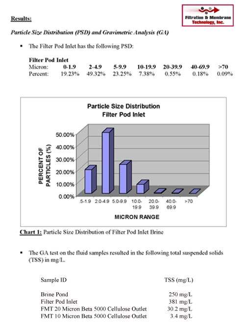 Your particles have a characterization profile which must be determined. Particle characterization is the process of identifying various particles by particle shape, size, surface properties, charge properties, mechanical properties, and microstructure. Your particles may be complex in shape, they may be hard or sticky. Samples will be tested to determine the particle size distribution to determine the correct membrane pore size. Various lab testing techniques are employed to characterize your particles such as microscopes, automated imaging, light scattering, and laser diffraction.
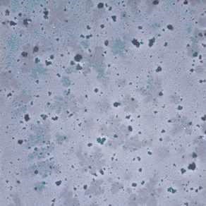
Particle Photomicrograph 50x
Particle testing labs including those of the filter supplier are employed to characterize the stream to be filtered. Once your particles are characterized the next step is to determine feasibility with a lab or pilot sized membrane system. In many cases, your process is proprietary or requires a controlled environment and testing must be performed onsite requiring rental systems whose data can be scaled to full-sized Industrial systems.
We have your process and particle data, what is next?
It is recommended to perform pilot testing in the lab or on site with lab sized ceramic membrane elements or larger systems that can be scaled to full sized systems. Some pilot units can be rented for testing your fluids and to train your personnel or because the fluids or gasses are delicate, dangerous or proprietary. The pilot testing will answer questions about pump sizing and type, actual permeate flow rates, fouling and cleaning cycles, and fine tune or prove the element selection,
How is oil removed from water by a ceramic membrane?
Ceramic membranes are highly hydrophilic and due to their physical composition also allows them to be oleophobic thus rejecting oil. They are employed for oily water and emulsified oil water streams which usually also contain particulates. The ceramic membrane surfaces can be modified to increase oil rejection from 95 to 97%. For most applications, a filterable suspended particle must be present to be removed by ceramic filtration.
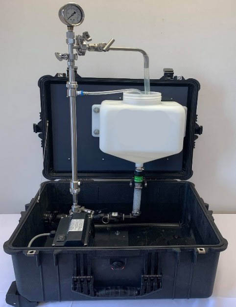
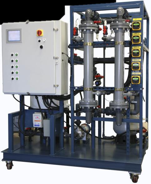
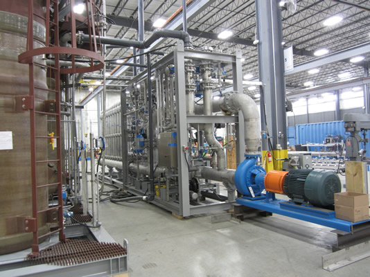
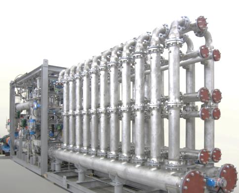
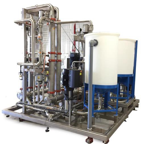
What does the equipment look like?
Pictured below are a suitcase sized test unit, a computer controlled automated pilot unit, and a full-scale system. The operation of the pilot units optimizes velocities, pressures, concentration factors, flux, permeate flow rate, recycle rates, fouling rates, backpulse and backflush timing.
What is pervaporation?
A novel application for ceramic membranes is pervaporation. Close boiling components like ethanol and water which have an azeotropic condition at their similar boiling points do not allow a separation greater than 95.6% employing atmospheric boiling. However, azeotropes can be broken employing the different diffusivity rates of the components through the ceramic membrane instead of their boiling points. A vacuum is applied to the permeate side of the membrane For example treating a 90% mixture from an evaporation process can produce 99.999% ethanol. For industrial purposes there are much more valuable close boiling mixtures which can benefit from employing ceramic membrane pervaporation.
Common applications for ceramic membranes:
Oil & Gas, Refining and Petrochemical
-
Produced water: steam flood, water flood, surface discharge, reinjection, reuse
-
Completion fluid filtration
-
Sulfuric Acid filtration for reuse
-
Workover fluid filtration
-
Disposal well reinjection
-
Desalter brine
-
FPSO slop water
-
EOR fluids
-
Oil filtration for oil recovery
-
Solvent Deasphalting
-
Vacuum Residual Oil Recovery
-
Pervaporation
Chemical Process Industry
-
Sodium bicarbonate brine filtration
-
Chlor-alkali brine filtration
-
Membrane biological reactors (MBR)
-
Acid filtration for recycle/reuse
-
Caustic filtration for recycle/reuse
-
Oil filtration
-
Pervaporation
Environmental
-
Oily Wastewater Treatment
Primary Metals Industry and Metal Finishing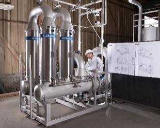
-
Heavy metals removal
-
Oil & grease removal
-
Dewater spent water soluble coolants and rolling oils
-
Caustic cleaner and degreaser recycle
-
Oil filtration for recovery
Marine industry
-
Bilge water filtration
Industrial Laundry
-
Wastewater recycle and reuse
Mining industry
-
Tailings pond filtration
Pulp and paper industry
-
Black liquor
Disaster relief
-
Emergency drinking water
Food and beverage industry
-
Fermentation broth clarification
-
Wine filtration
-
Beer filtration
Recovery of valuable components from food waste
-
Membrane biological reactors
-
Caustic cleaner recovery
-
Natural spring water

-
Pervaporation
Biotechnology industry
-
Fermentation broth clarification
Nuclear power industry
-
Wastewater
Why should I consider ceramic membranes for my project?
Cross-flow and flat sheet ceramic membranes should be on your list as a filtration solution even if you are only familiar with systems such as disposable filters, candle precoat backwash systems, belt filters, filter presses, oil absorbers, crystallization, or evaporation. These systems are employed worldwide for numerous filtering applications.
Additional information is available from FMT-Houston, please call or E-mail us.
E-Mail: fmt-houston@att.net
Phone: 713-870-1120
Please review the data sheets listed below for additional technical details:
Technical data sheets for ceramic crossflow membranes:
CeraMem® Skidded Systems Data Sheet
Kleansep™ Ceramic Membranes For Food and Pharmaceutical Applications:
Filtration & Membrane Technology, Inc.•370 Camden Hills W., Montgomery, TX, 77356•Phone: 713-870-1120
E-Mail fmt-houston@att.net